Sturdy Edge Module (StEM)
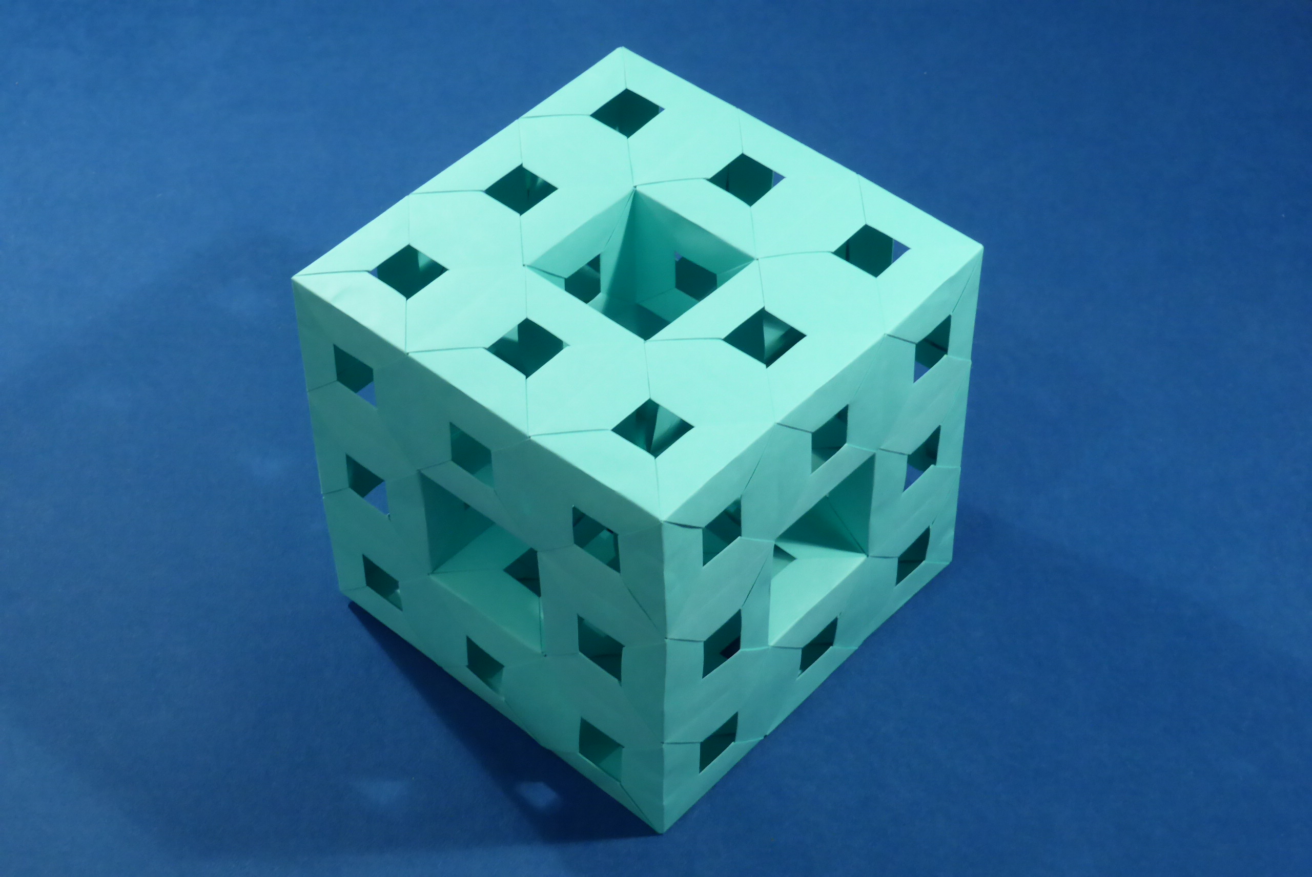
StEM is a very versatile module which can be used to make a number of very different objects. Three units can build a triangular 45-degree pyramid, so anything that can be made with Sonobe units can also be made with StEM. In addition, objects with square, triangular and hexagonal faces can be made. The latter two require a small adaptation of the units and result in faces which are not flat: the triangles/hexagons will stick outwards or point inwards a bit. Since the hole in the middle of the square face is ⅓ of the edge length, this unit is well-suited for making Menger Sponges. In most uses, StEM is an edge unit, but when folded in half along the shorter axis, it can be used as a face unit which behaves quite a bit like Sonobe unit (alternatively, you can see it still being an edge unit but with the edge going along the shorter instead of the longer axis of the module).
This unit is quite simple and after inventing it, I found out that a number of other people had had the same idea before. See the model’s page for details.
Instructions for other peoples’ versions (in print media)
I got the information below courtesy of Dirk Eisner:
Tomoko Fuse’s […]. She has another folding, which is equal to your SEU, in Unit Origami Wonderland. This book is in Japanese. She named it something like 45°-60°-unit. Here the second end of the module is different. Francis Ow named it 90-degrees unit. He has a diagram in his booklet Modular Origami. He started with a 1/6 segmentation, but then it is similar to your unit. With my notation I would name it p45f90 -|- p45f90 unit. I have published my way, e.g. in Convention Book 5OSME, Singapour, 2010 , Origami Christmas Book, edited by Anna Kastlunger, 2012 or Convention Book Origami Deutschland, Weimar, 2013.
Phototutorial
StEM can be folded from paper of any aspect ratio, but was designed with square paper in mind. Square paper results in an edge module which is quite bulky and has, in my opinion, better-looking proportions than SEU folded from 2:1 paper which looks a little skinny. Square paper is also closer in line with the classical origami rules.
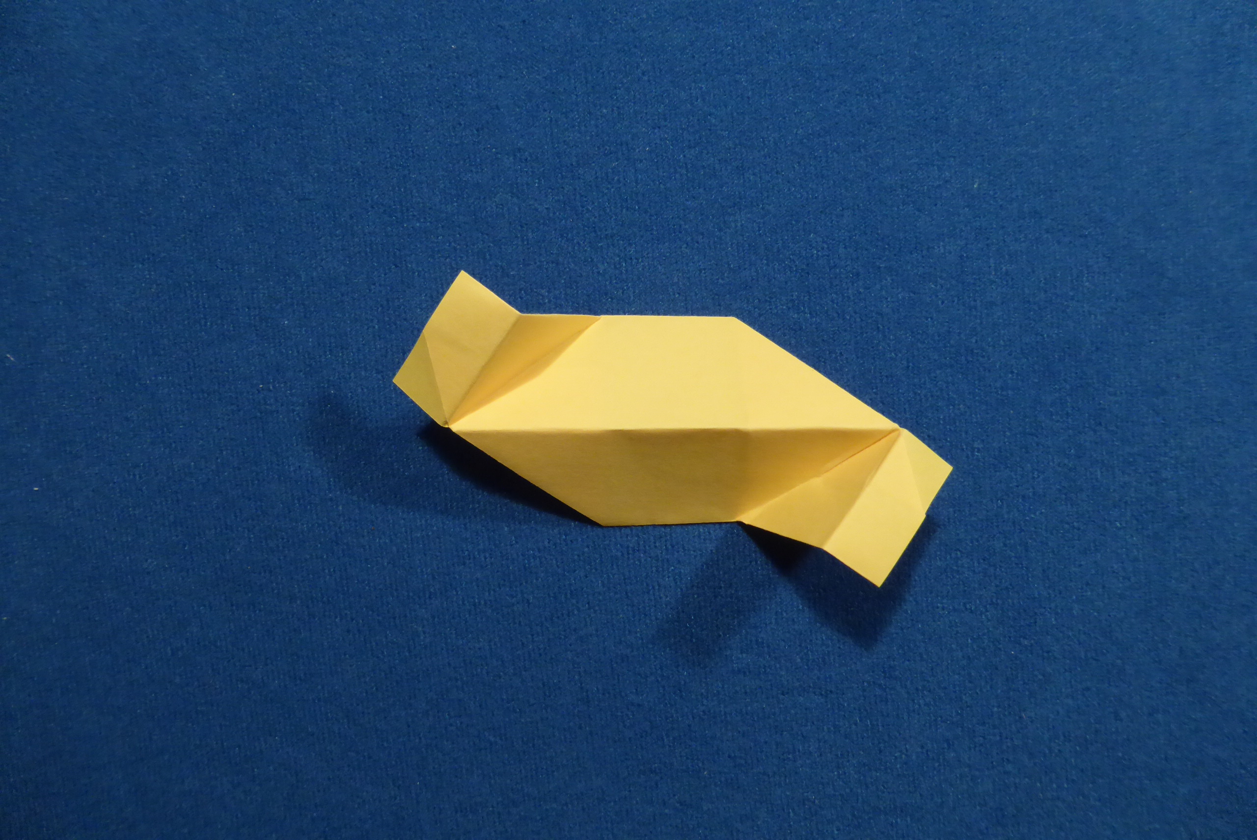
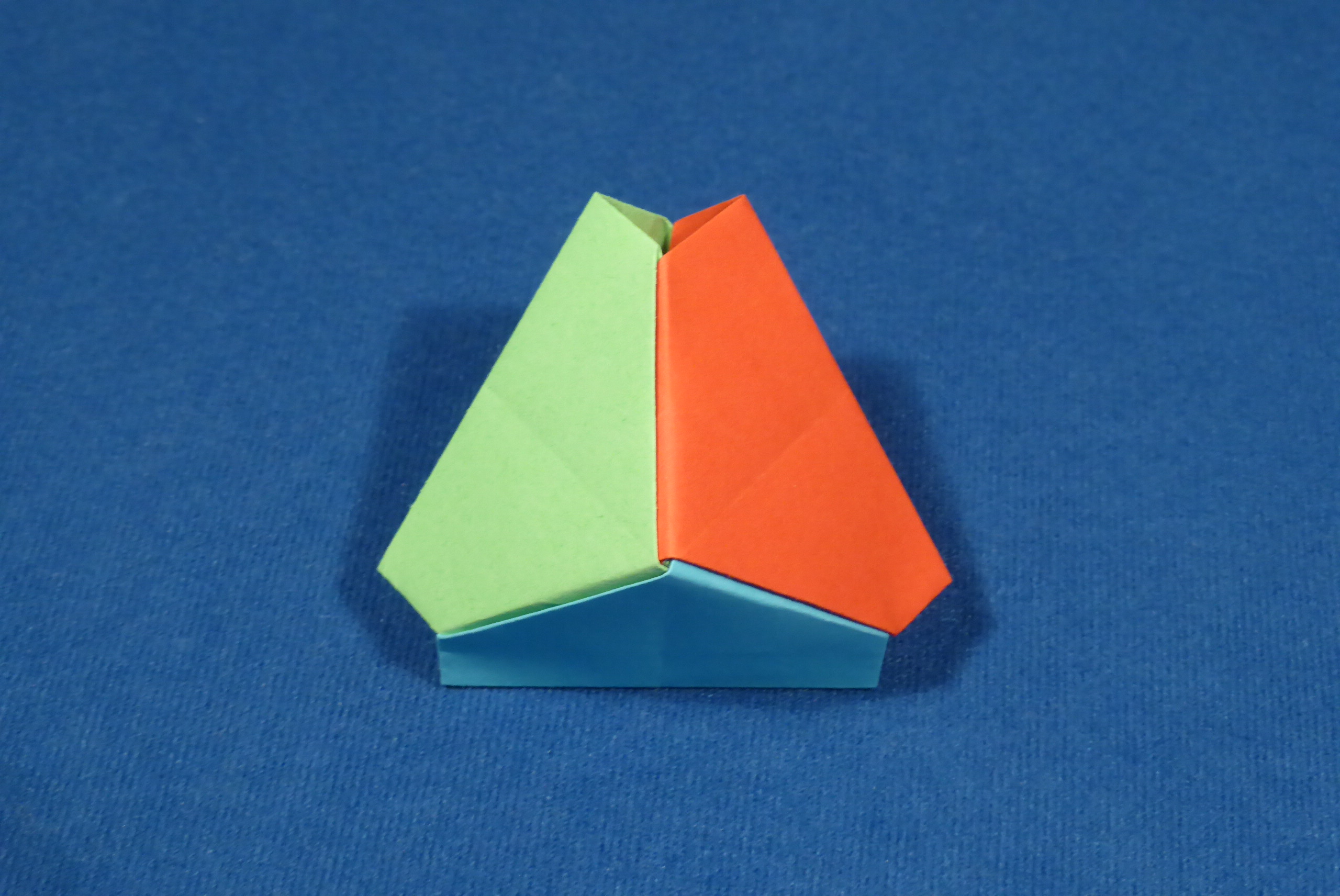
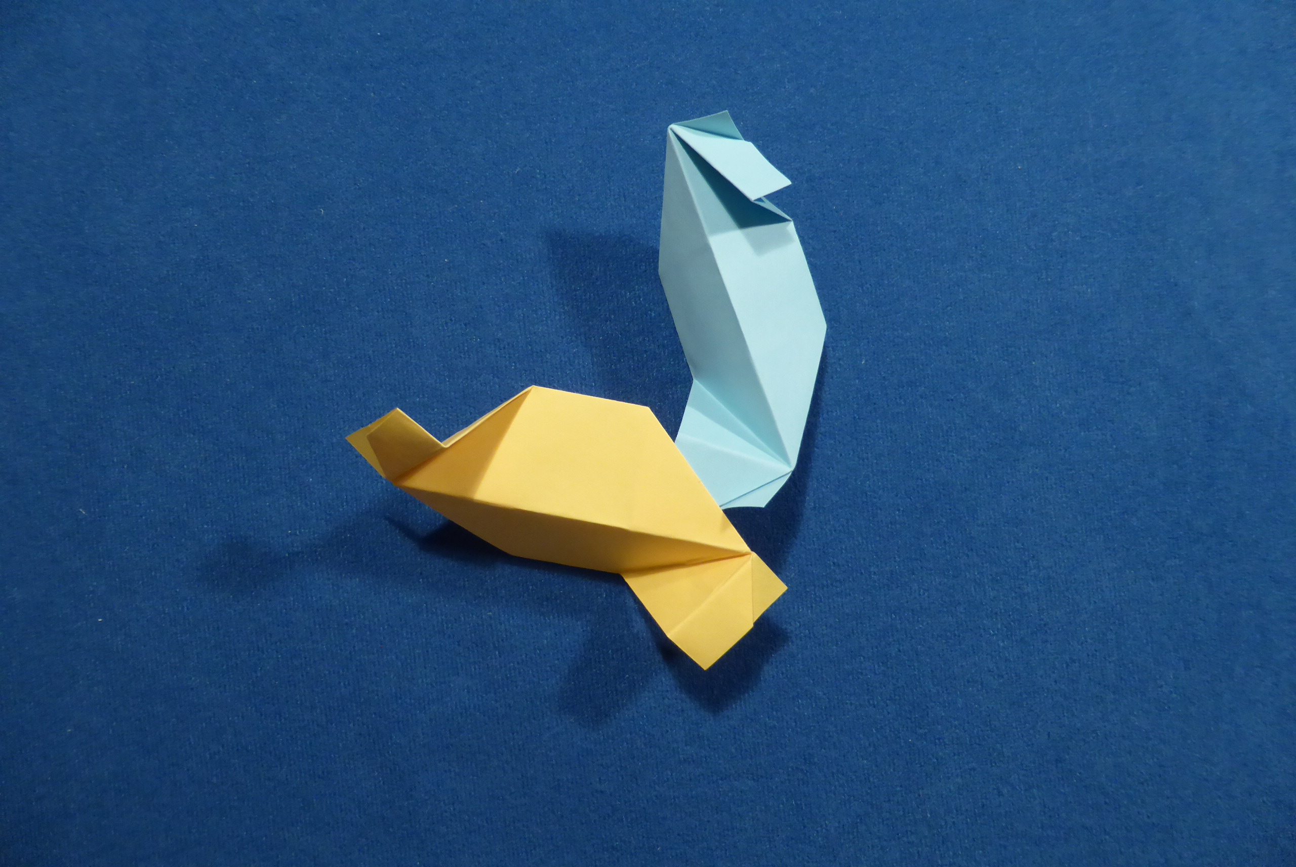
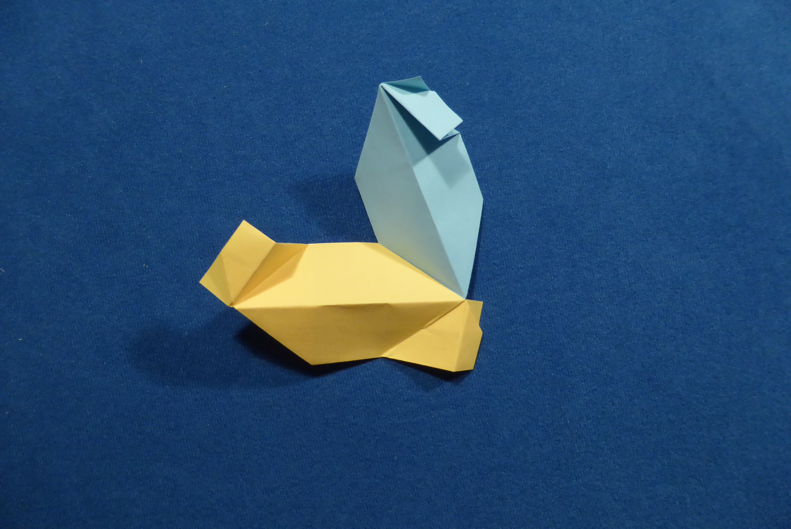
Finished module and sample usage
Finished module, variants for outwards and inwards facing triangular faces, respectively:


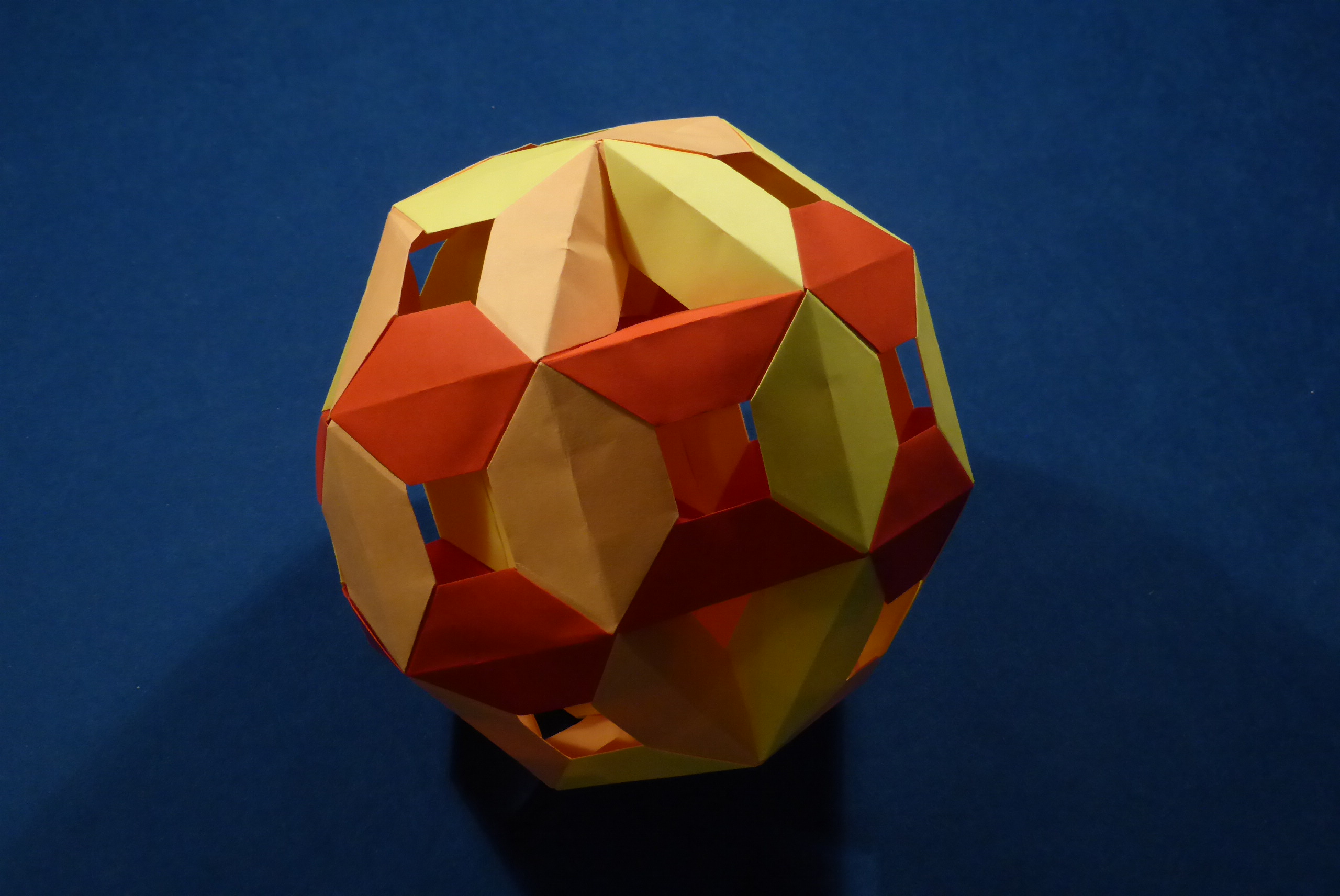
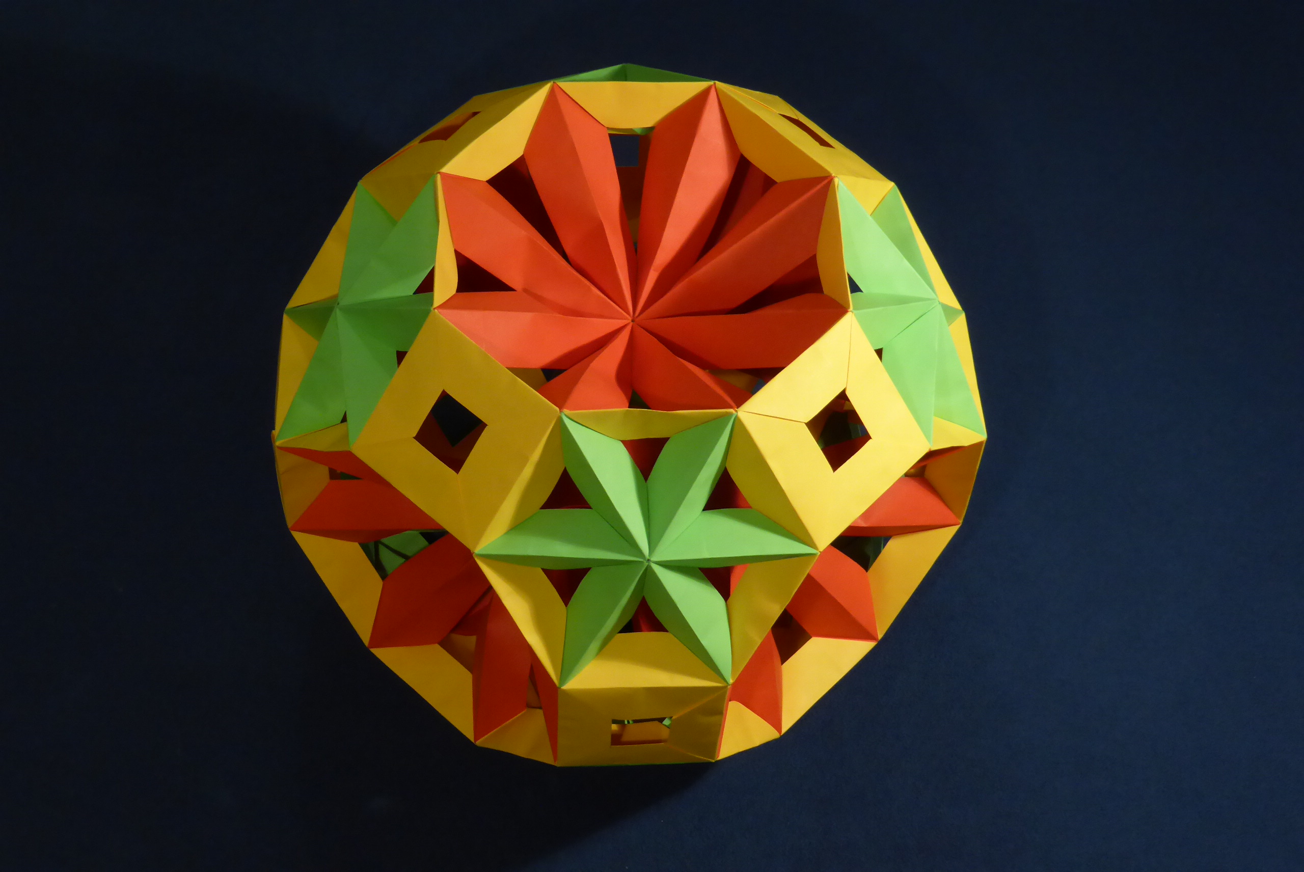
Examples of finished models, using modules made from paper of different proportions:
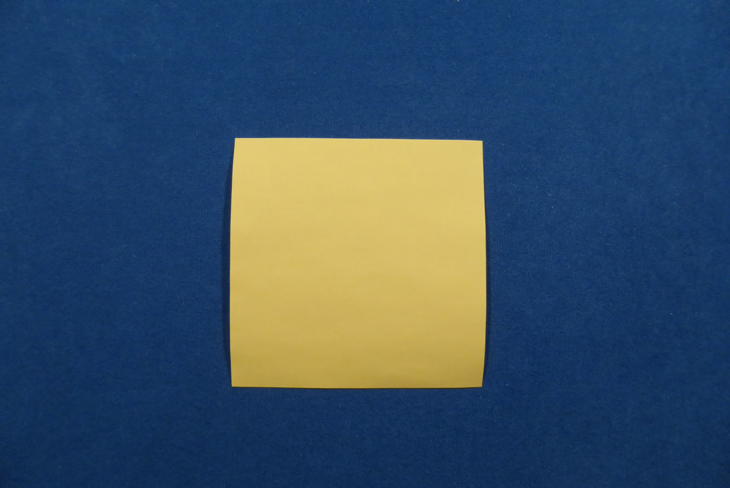
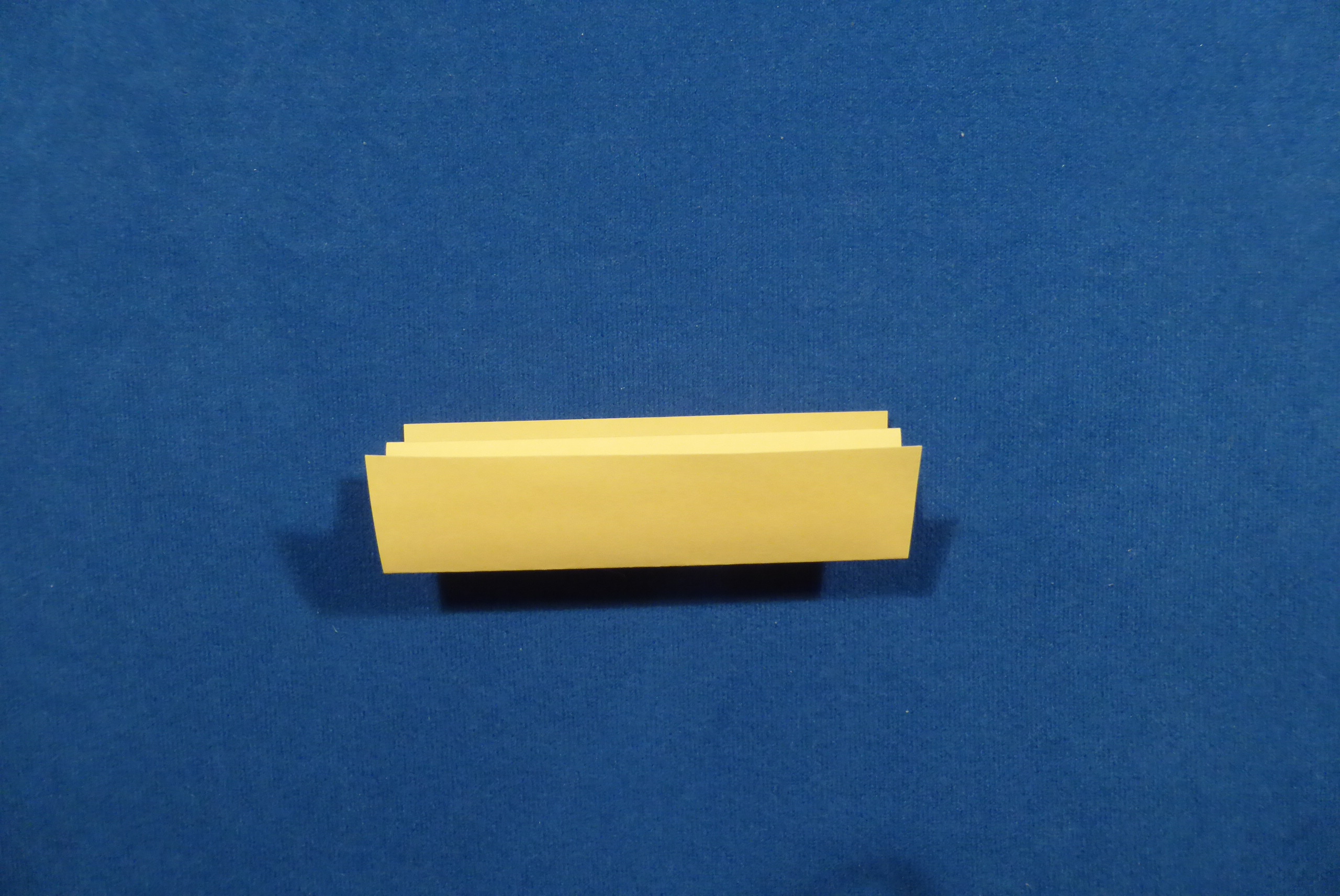
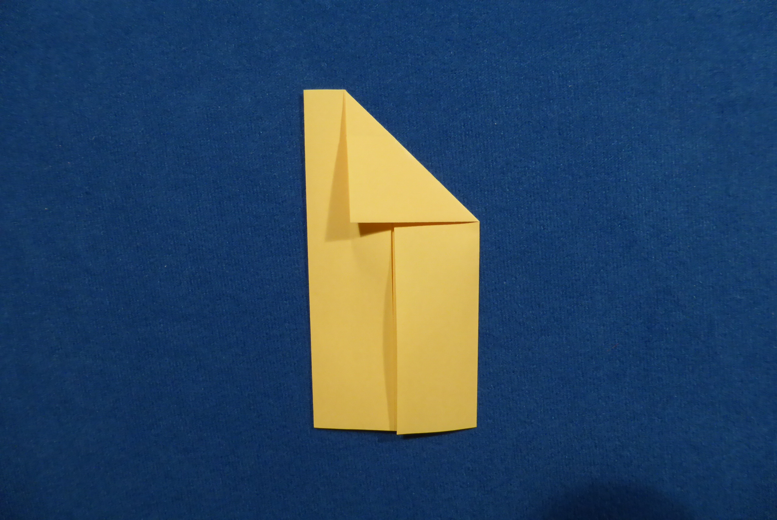
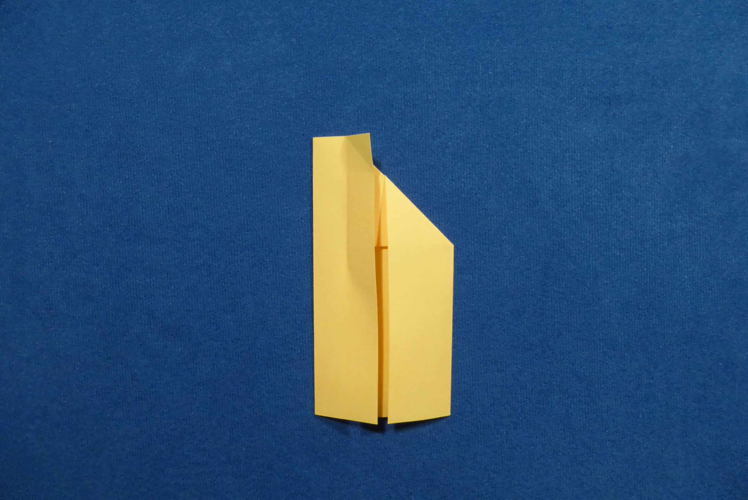
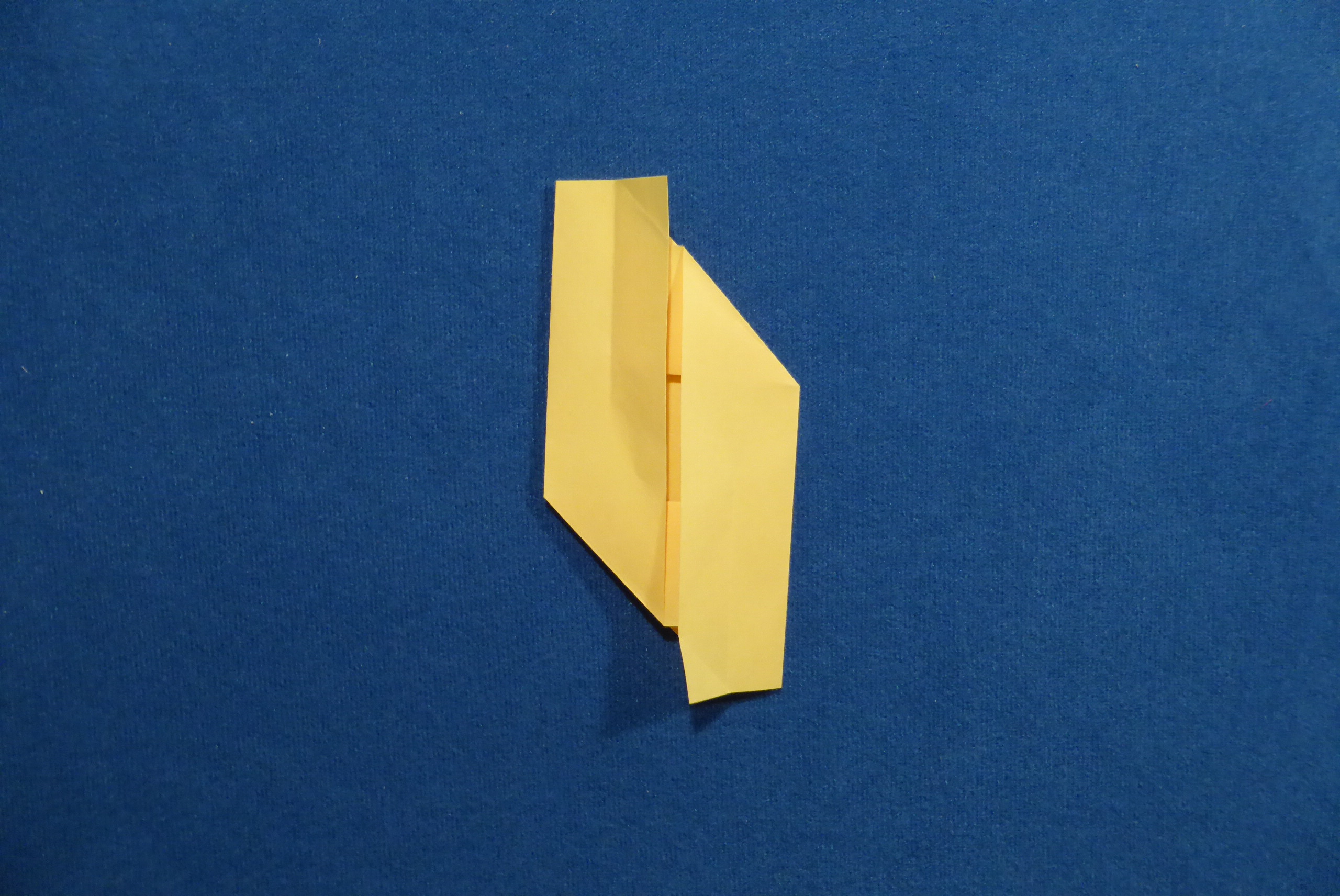
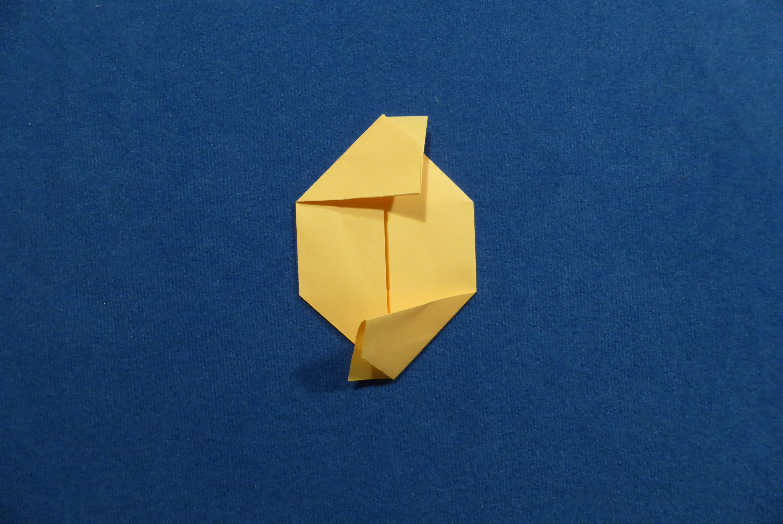
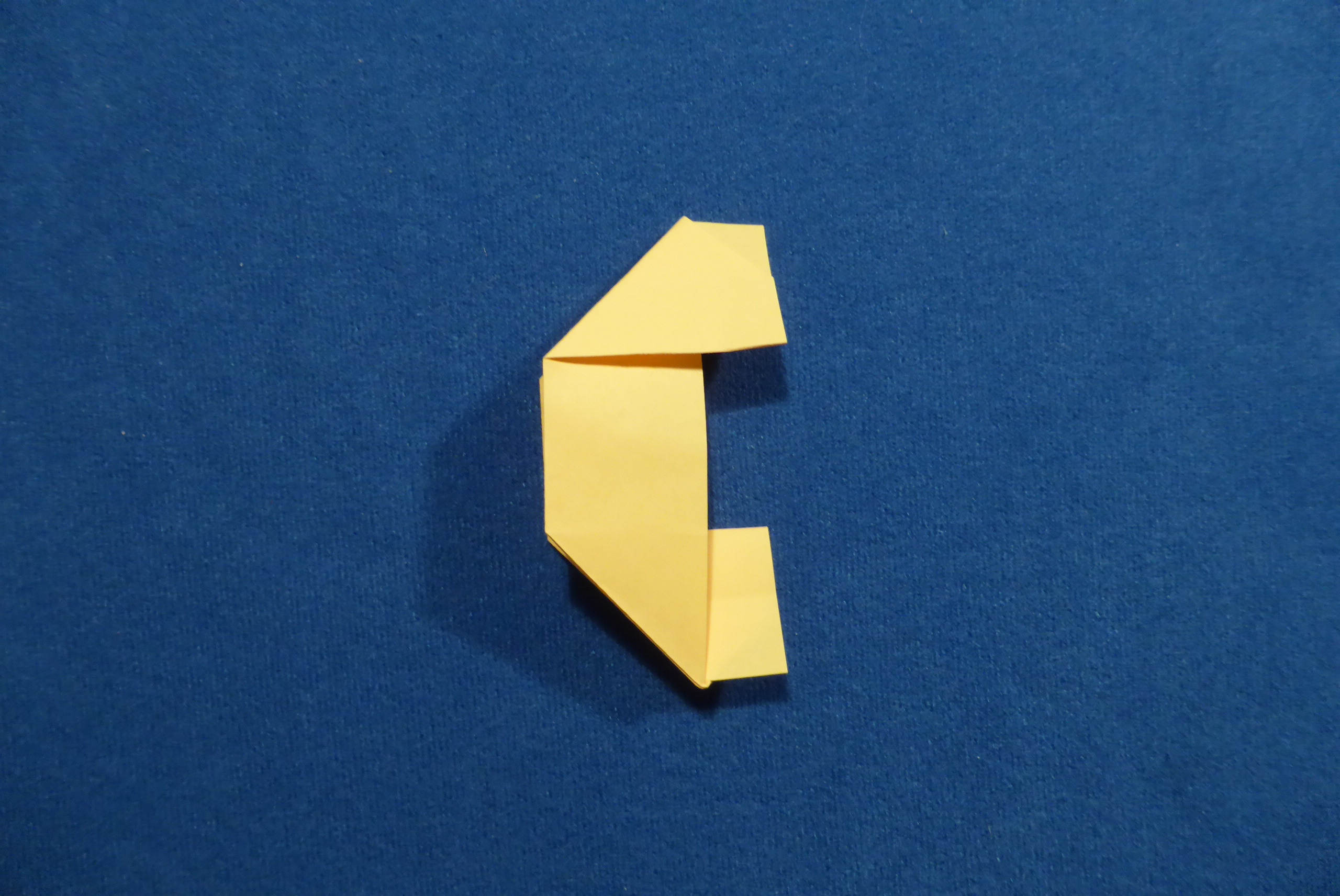
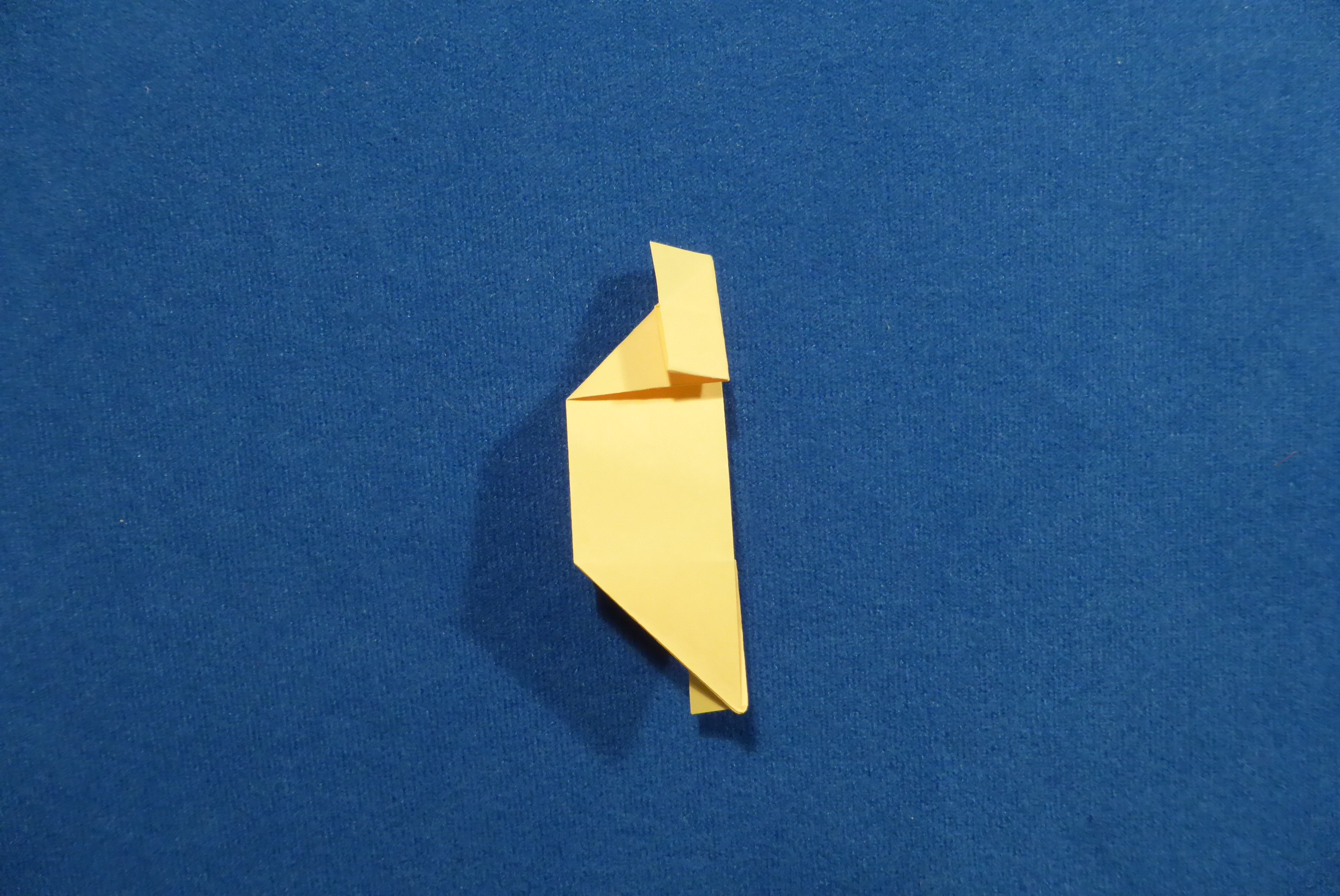
Folding the Sturdy Edge Module
Instructions show folding from a square, but paper of other proportions can be used as well.


Assembling the modules
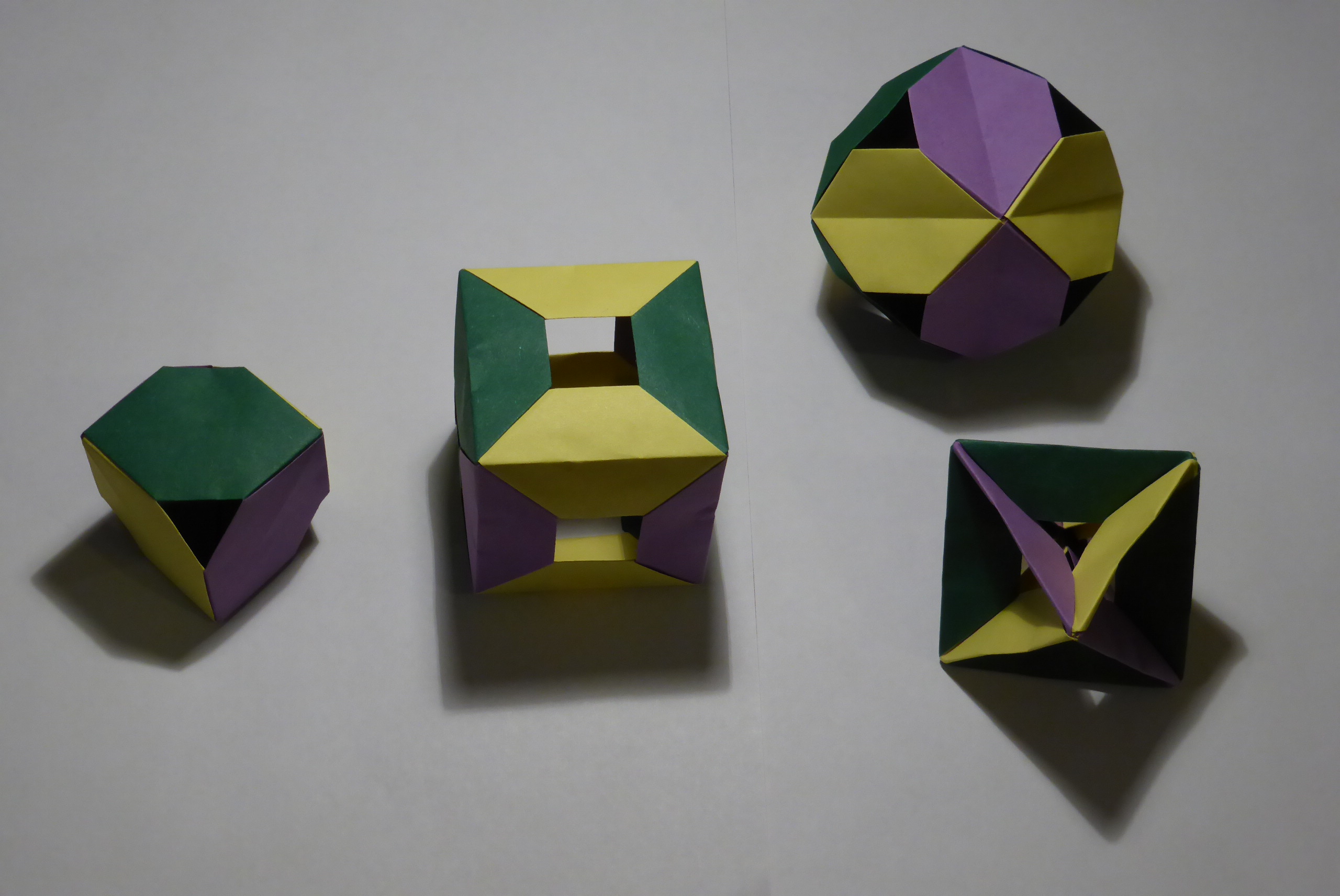
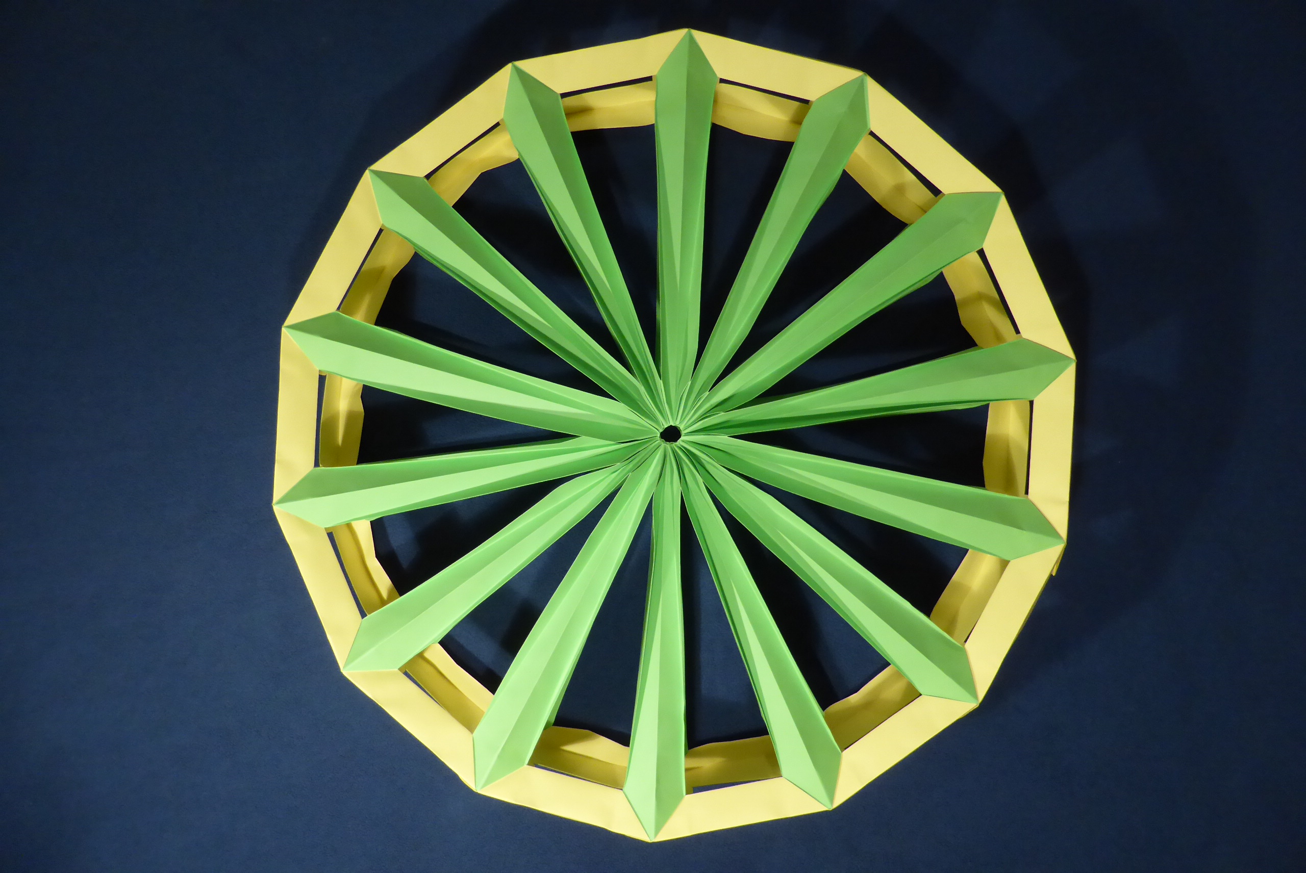
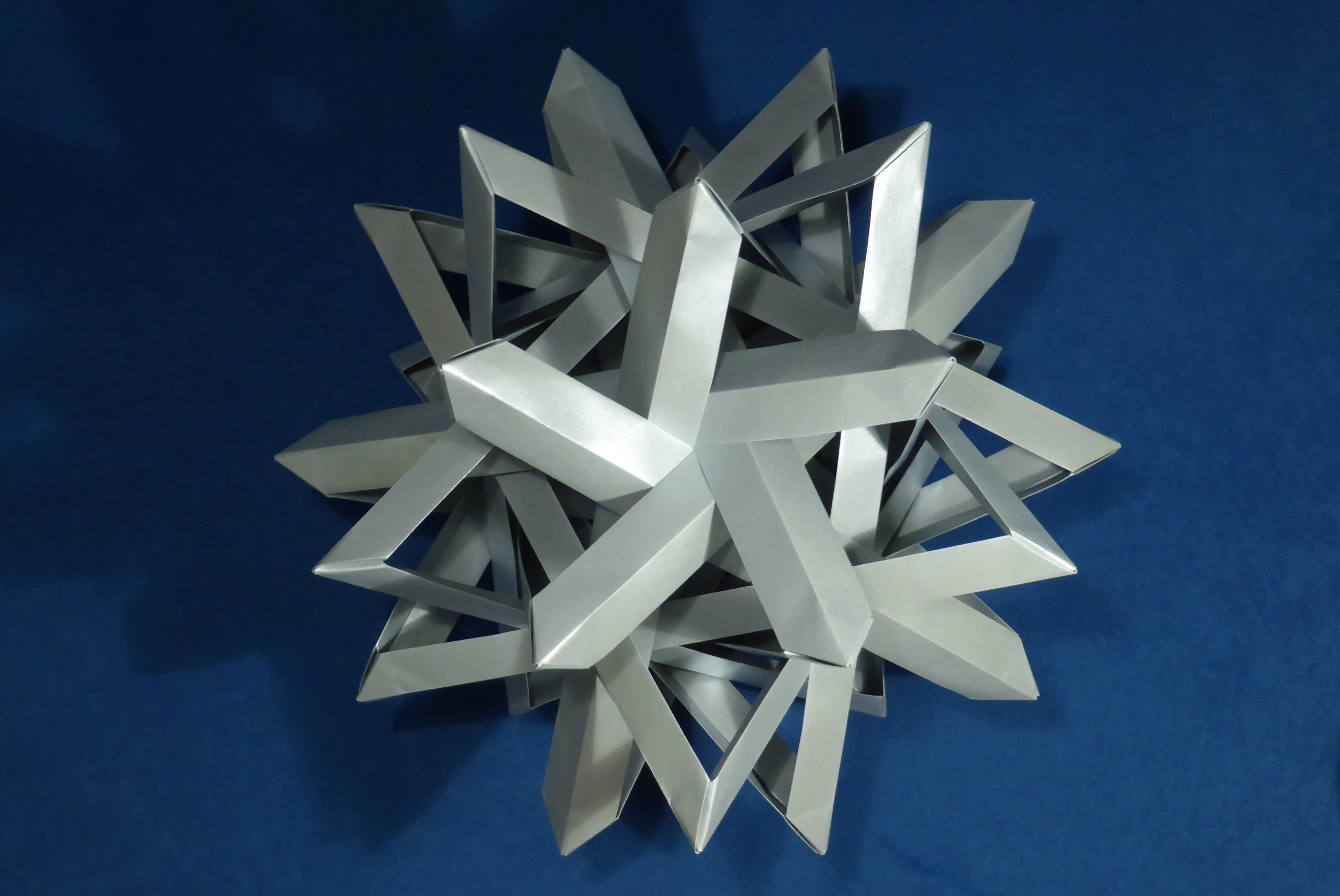
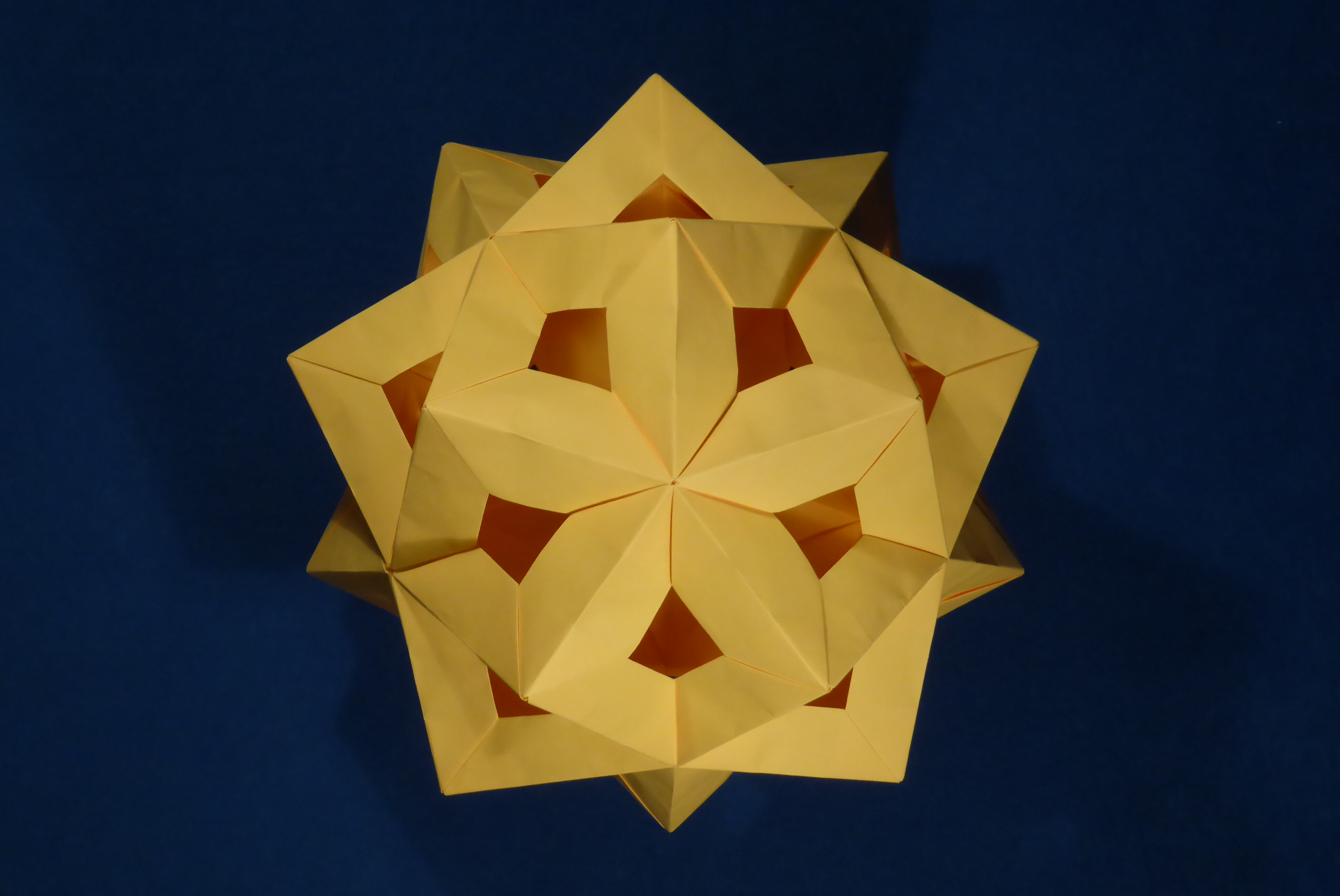
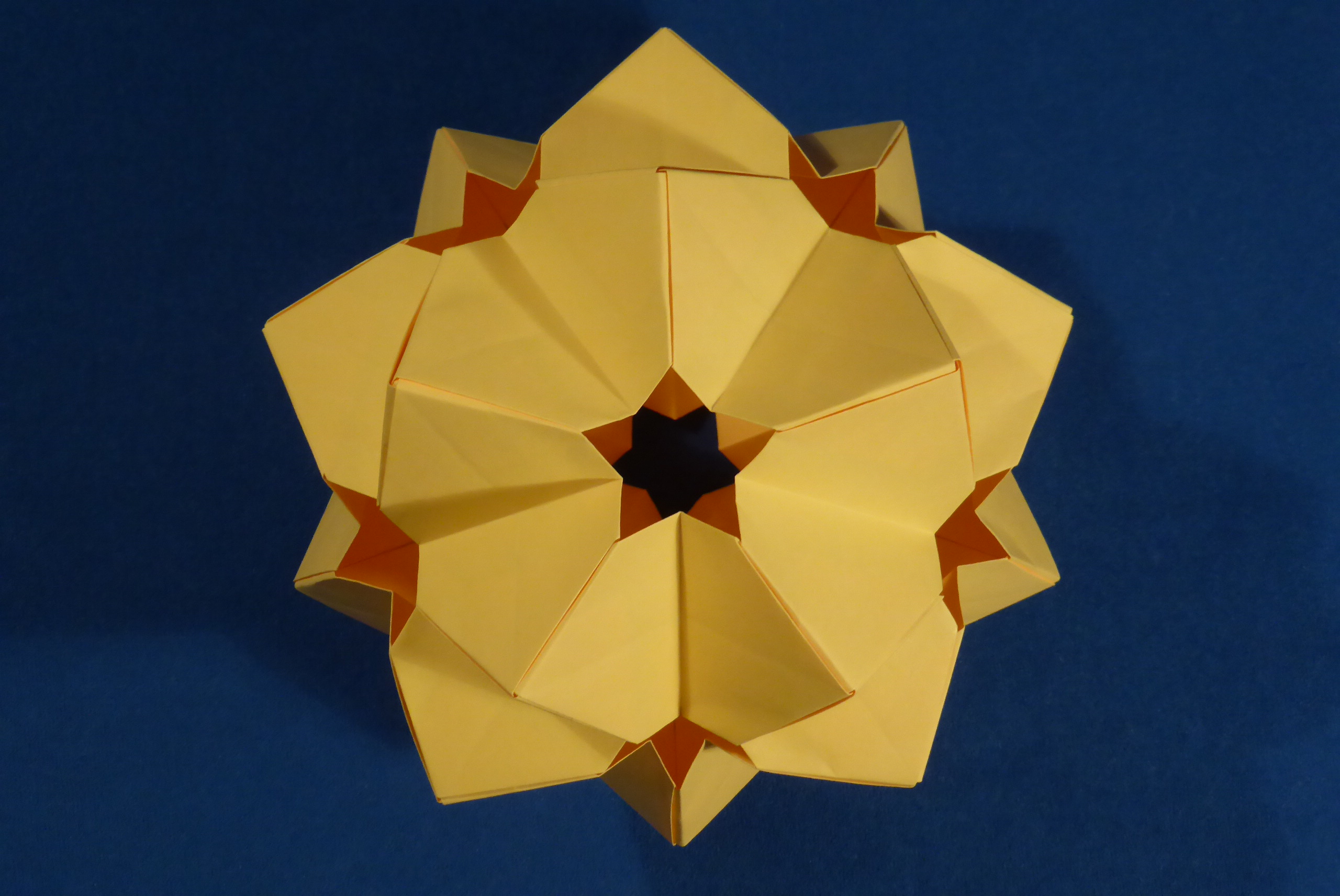
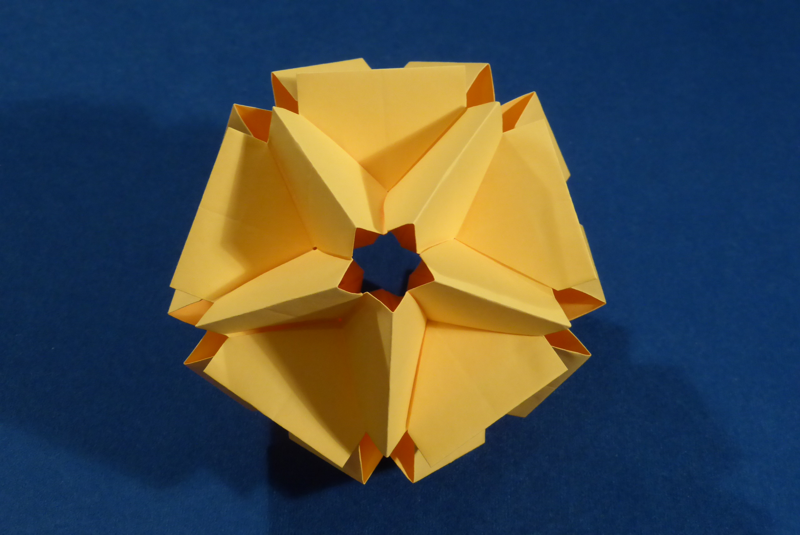
Similar to many other edge units, StEM modules can be connected in many different ways. The angle between the axis and the tip is 45°, so a flat connection results in square faces. If squares are creased along their diagonals you can create spiky balls (as with Sonobe units). Eqilateral triangles can be made with the edge units pointing inwards or outwards, and triangles can be used to create pyramids which cover pentagonal faces. Hexagonal faces can be assembled from six coplanar triangular “faces”.
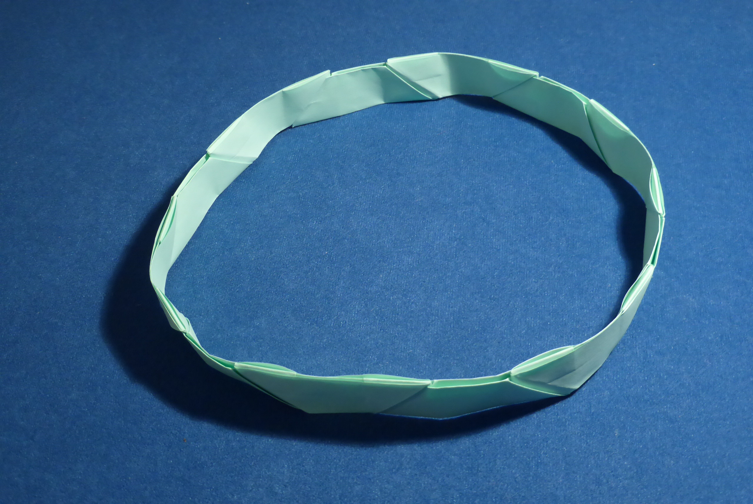
Additional folds allow the module to be connected into thin and long “belts”. You can find many examples of assemblies using this module at the top of this page.

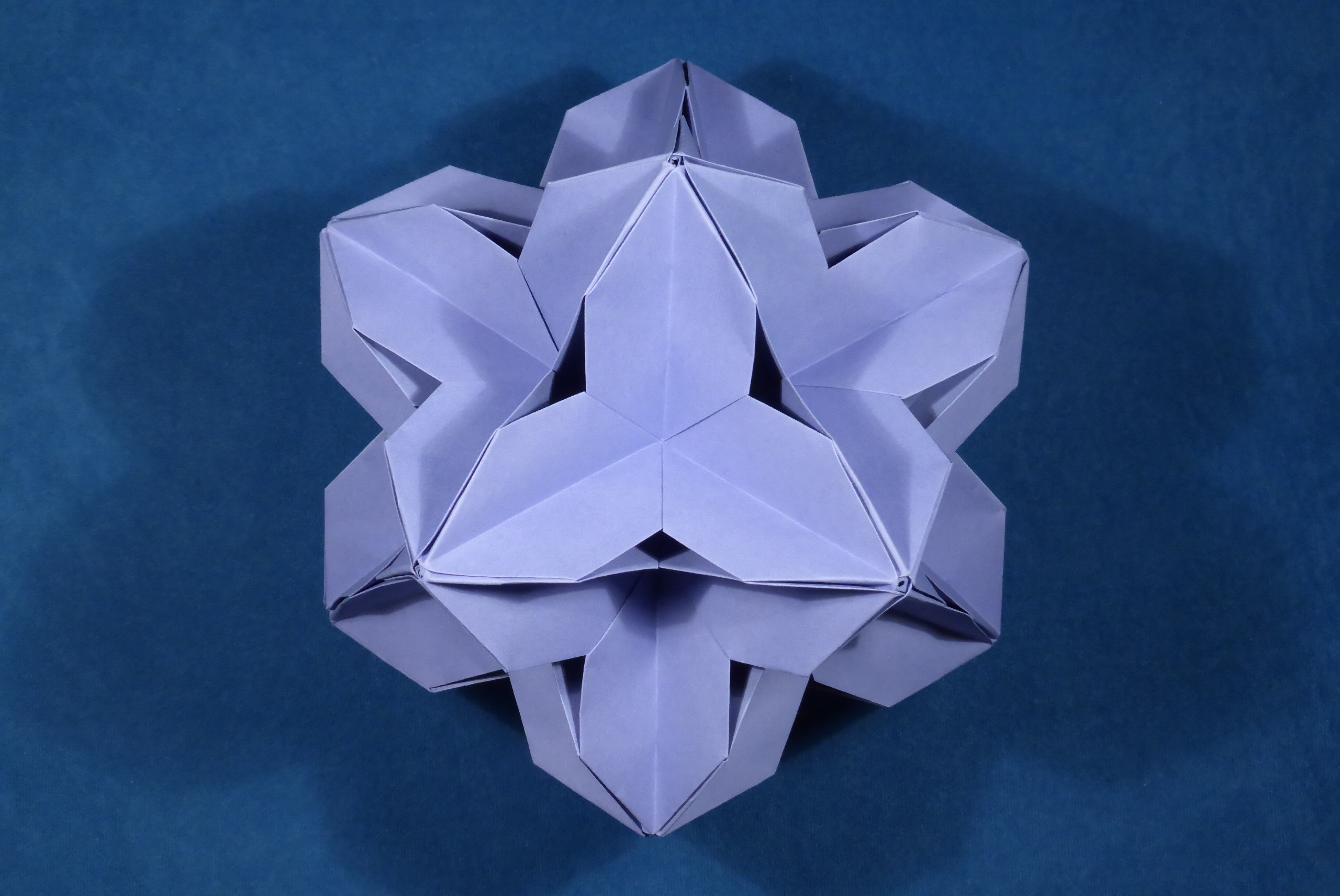
Normally, as in the assembly examples above, StEM is used as an edge unit. However, it can also be folded in half along the shorter axis and used as a face unit. In this setup, it is similar to a Sonobe unit whose sides were cut off. Dave Mitchell invented this “face configuration” (under the name Cube-Corner Star) as early as 1993. An example of this connection method can be seen in the models below.
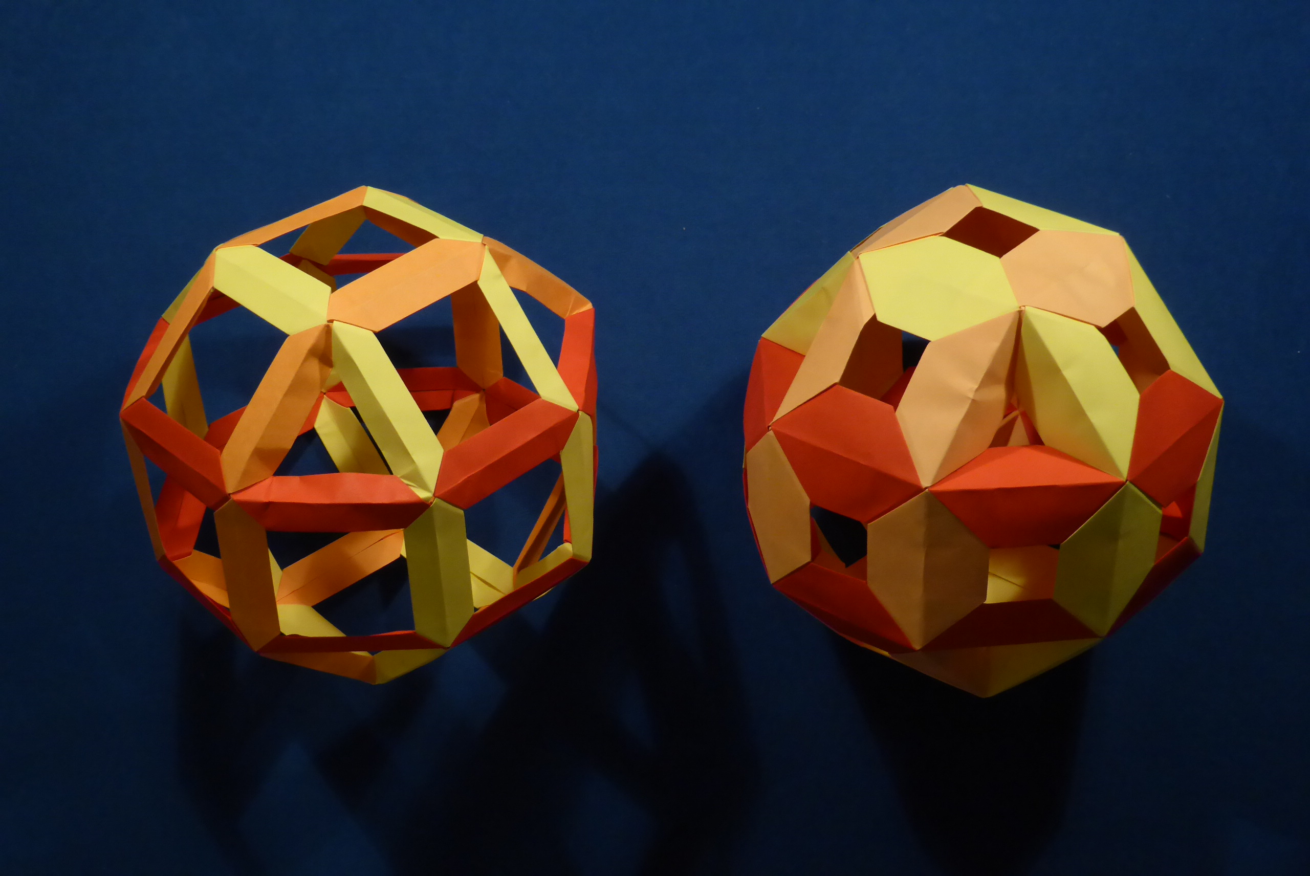
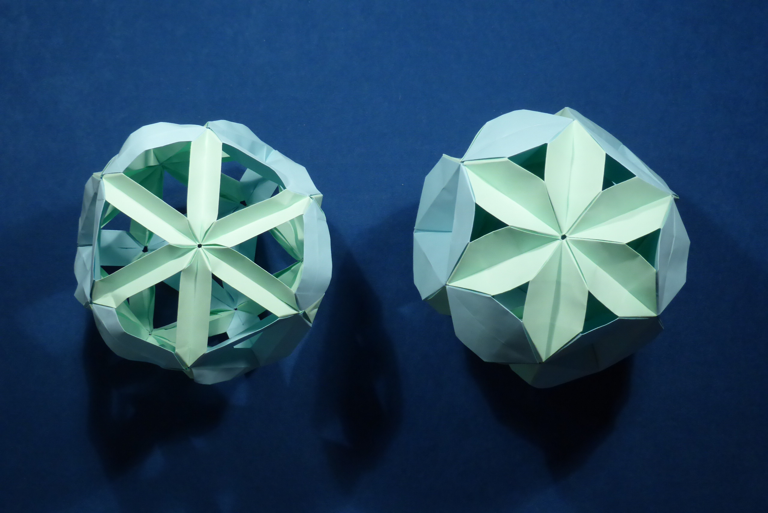
Comparison between SEU and StEM units
In each of these pictures, the model on the left was folded from SEU units, a related design, made of 2:1 paper and the model on the right was folded from StEM units made of 1:1 paper.
Comments